Each of the Caliper2PC ports (P1 - P6) have an I/O input and an I/O output pin. While the I/O output pins can be used to switch spindle motors or coolant pumps through relays, the I/O input pins can be used for data capturing through switches. The I/O input pins are internally connected to pull-up resistors, so that simple switches can be connected between the I/O input pins (pin 6) and GND (pin 1). As soon as a switch is pressed it connects the I/O input pin with GND, so that the level changes from "High" to "Low". This level change is transmitted to the host and triggers an event within the Caliper2PC software. The event triggered by the pressing of the switch can be redirected by the Caliper2PC software to write a set of data into an Excel table, or into a *.csv file, or into the clipboard or into the keyboard emulator. The data set can contain the readout values of any device connected to the interface. The Measuring index, and the date as well as a timestamp can be added to each captured value. Using the Caliper2PC software's "Auto Capture" feature a capturing switch connected to any port (P1 - P6) can be used to capture data from all ports. If a free port is available, a RJ45 patch cable can be connected to a switch only (without an encoder). This way the measuring devices (eg. calipers) and the capturing switch (for example a foot switch) may be located at different locations (calipers may be on the desk while a foot switch can be on the floor). Alternatively the capture switch can be mounted on the measuring device itself. The following description shows how a capturing switch can be mounted within the housing of a simple caliper. The caliper shown here is a Type A device, so a BIN6 adapter between the caliper and the interface is not needed in this case. The caliper must be connected to the Caliper2PC interface through a cable with at least 5 wires (GND, -1.7V, DATA, CLOCK and I/O-INPUT). The cable's diameter must be small enough to fit into the caliper's housing.
|
|
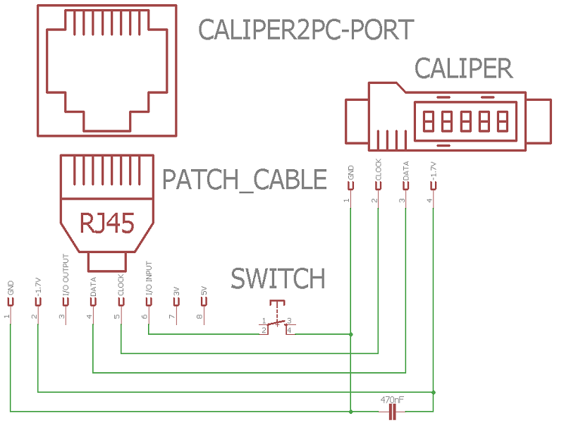
Pin assignment of a Type A caliper with a capturing switch.
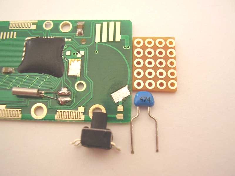
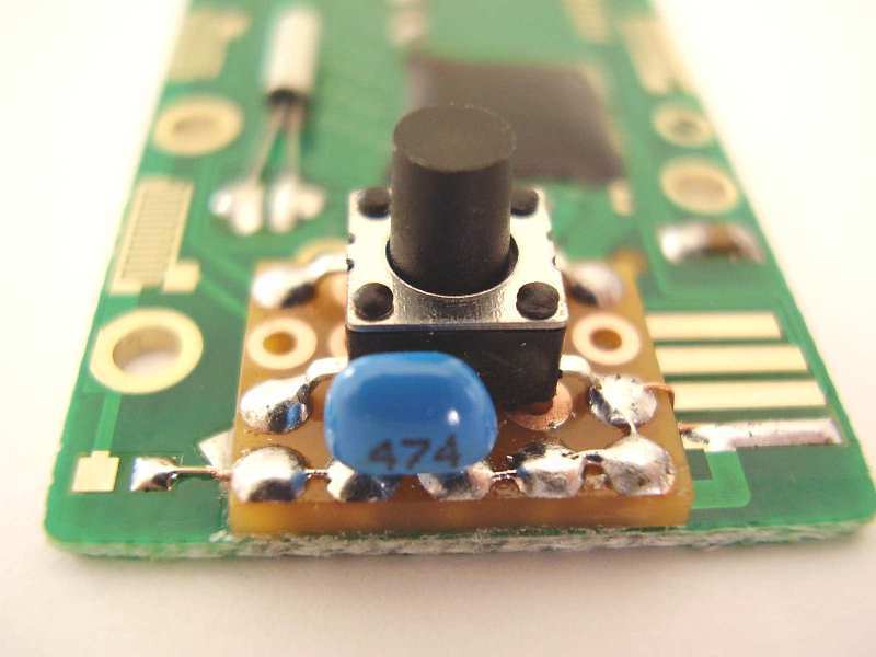
The caliper's battery contacts are not needed because the caliper is powered by the data cable. After the contact pads are desoldered, the remaining solder is removed from the encoder PCB using desoldering wire. A 6mm x 6mm SMD tactile switch is used as a capture button. The switch and a 470 nF capacitor are soldered on a precut piece of breadboard. The breadboard is glued to the encoder PCB with superglue. The breadboard's position on the encoder PCB is adjusted according to the capture button's position. It is located in the center of the battery cover. Finally the breadboard is connected to the encoder PCB through a thin copper wire.
|
|
Encoder PCB, capture button, capacitor and breadboard.
|
|
Encoder PCB with glued breadboard with capture button and capacitor.
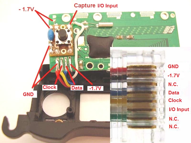
The encoder housing is machined with a grinding tool (eg. Dremel), so that the PCB and the glued-on breadboard fit neatly into the housing. Finally the data cable with the RJ45 connector is soldered to the encoder PCB according to the pin assignment.
|
|
Pin assignment RJ45 data cable.
A hole matching the capture button must be drilled in the battery cover. Subsequently, the battery cover is pushed back into its seat in the encoder housing.
|
|
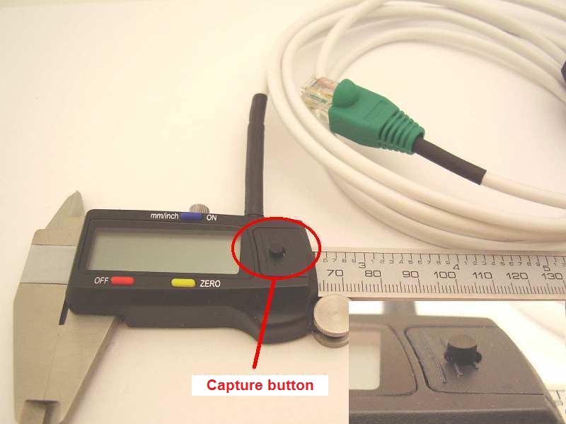
Caliper with mounted capture button.
After the LCD display and the buttons are placed in the housing, the caliper is screwed together and is ready to be connected to one of the Caliper2PC interface's ports.
top
Copyright © Dipl.-Ing. Tomer Lanzman. All rights reserved.