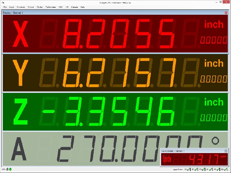
· DRO (Digital Readout)
|
|
fig. 1: PC - based DRO (digital readout).
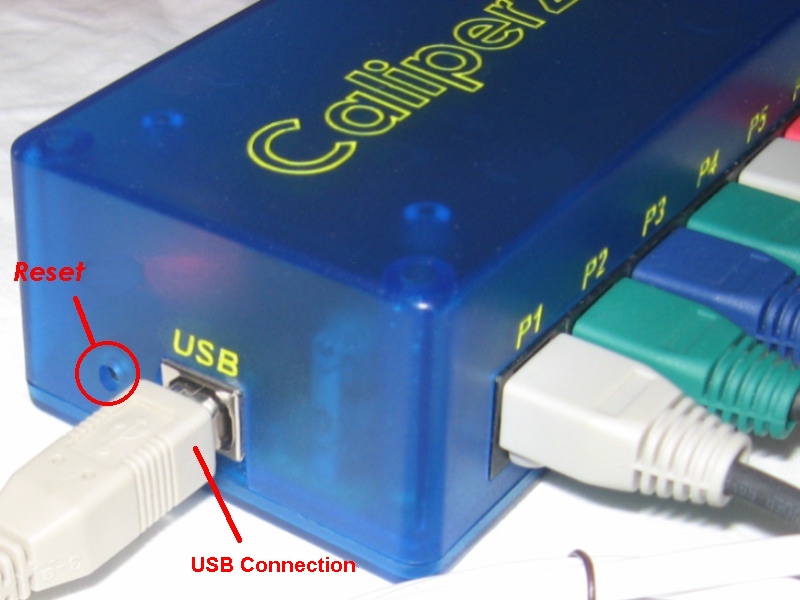
· The Caliper2PC Interface is user-friendly connected to the PC via USB (type B see fig. 2). No external power supply is necessary to operate the Caliper2PC Interface.
|
|
fig. 2: Caliper2PC Interface, USB port, reset key to reset the interface.
· A negative supply voltage is generated by the Caliper2PC Interface to supply the digital scales. For the optical sensors of the tachometers regulated DC voltage is supplied.
· The Caliper2PC Interface possesses six entrance ports to connect up to six digital scales (see fig. 3). They are connected via 8-pole RJ45 network cable connectors. In addition, the 8-pole entrance ports offer the ability to connect Capture Buttons, with which measured values can be captured. Alternatively, micro switches can be connected as end switches or reference switches to reset the DRO.
|
|
fig. 3: Caliper2PC Interface, entrance ports P1 P6, pin assignment for RJ45 connectors.
· All six 6 displays can be reset within the Caliper2PC Software. The scales connected to ports P1 - P4 can also be reset to zero at the scales themselves.
· Caliper types "A" and "B" are automatically recognized and supported by the Caliper2PC Interface.
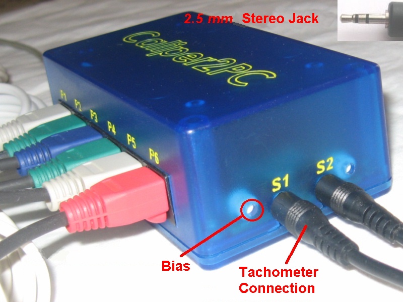
· The optical sensors for the tachometers are connected to the Caliper2PC Interface by standard 2.5 mm stereo jacks. To enable the user to use photo diodes or photo transistors of his choice and to be able to work independent of the surrounding lighting conditions, potentiometers to adjust the ideal operating point have been integrated (see fig. 4).
|
|
fig. 4: Caliper2PC Interface, sensor connectors for tachometers, potentiometers for adjustment.
· The Caliper2PC Software includes an appealing 7-segment display in LED and LCD style. The displays size, colors and fonts can individually be defined in the software. In addition, the display can be freely labeled by the user, e.g. X-, Y-, Z-axis. The Caliper2PC Software is more than a simple digital display and offers its users on top the following output options:
![]() Summation of measured values from other
channels (e.g. for cross-slide and carriage)
Summation of measured values from other
channels (e.g. for cross-slide and carriage)
![]() Saving of up to 10 tool offsets per
channel (e.g. cutter radius offset)
Saving of up to 10 tool offsets per
channel (e.g. cutter radius offset)
![]() Voice output
Voice output
![]() Output into clipboard
Output into clipboard
![]() Output into a file
Output into a file
![]() Output into an open editor window (e.g.
WordPad, Notepad etc.)
Output into an open editor window (e.g.
WordPad, Notepad etc.)
![]() Output into Excel maximal and minimal
limit values can be defined (if the limit values are exceeded or under-run, the
measured values can be displayed in colors defined by the user)
Output into Excel maximal and minimal
limit values can be defined (if the limit values are exceeded or under-run, the
measured values can be displayed in colors defined by the user)
![]() Output into a software interface, a
feature that enables the users to integrate their own developments in C# and VB
(API provided in a DLL).
Output into a software interface, a
feature that enables the users to integrate their own developments in C# and VB
(API provided in a DLL).
· The Caliper2PC Interface features a high-quality, slightly transparent, CNC-milled box with an industrially produced PCB.
Orders: The fully assembled and tested Caliper2PC Interface can be ordered here at the price of US $210: caliper2pc@gmail.com
top
Copyright © Tomer Lanzman.
All rights reserved.